ISAC Operator Training Lecture:
Tuning and Slits
Rick Baartman
What is a beam?
Answer: a group of particles traveling more or less in the same direction.
Q: Why can't they be perfect? I.e. why not travel in exactly the
same direction?
Look at an ion source. Atoms are ionized by hitting them hard enough. How
hard? Ionization energy is typically on order of 3 eV. So a typical
energy before extraction is 3 eV. After extraction, it is 30 keV, but it
will still have the same transverse momentum.
What is beam quality?
Beam has high quality if it is small and its divergence (rate
of spreading) is also small.
But beam may be high in quality and nevertheless violate these two
conditions.
So we need a better definition.
`Phase' space
Particles can be characterized by position (x) and momentum, or direction
(q). So on an (x,q) coordinate plane, every particle can be
assigned a point. Look at our 3 examples again:
Now it is easy to see why case C is high quality even though it corresponds
to large, divergent beam. The area it occupies in phase space is zero.
This area is called `emittance'. It is related to entropy: with good
practices, it is conserved, but it can increase and it's difficult to make
it smaller.
Liouville's theorem: Under the action of conservative forces, emittance is
conserved.
Real life emittances
Besides the (x,q) coordinate plane, there is also the (y,f)
coordinate plane. The two emittances are not necessarily the same.
 Also, notice the lack of a well-defined boundary. This means "emittance"
is a fuzzy term; sometimes we say e rms, sometimes e90%, etc.
Also, notice the lack of a well-defined boundary. This means "emittance"
is a fuzzy term; sometimes we say e rms, sometimes e90%, etc.
How does e relate to beam size?
A good emittance from the surface source is about 9 pmm-mrad. The
p is there to remind that you must multiply the 9 by p to get phase
space area. But actually, the real physics definition of emittance is area divided by
p. So for physics formulas, we say
(note:
1 mrad=1/1000)
Since this is a 2D quantity, you would probably guess that beam size is
proportional to square root of emittance. This is correct. In fact, the
half-size a is
where b T is a scaling parameter called the `Twiss beta function': it contains
the focusing information; it is large where the beam is large and small
where the beam is focused to a small spot.
Examples
At slits 24 and 26, bT=0.85 m, in both H and V
directions. Therefore, the half-size a=�{9×0.85}
mm=2.75 mm, or the correct slit size is 5.5 mm.
At the pre-separator slit (IMS:YSLIT0), bT=0.11 m
(horizontally). Therefore, the half-size a=�{9×0.11}
mm=1.0 mm, or the correct slit size is 2 mm.
At the mass selection slit (IMS:YSLIT11), bT=0.03 m
(horizontally). Therefore, the half-size a=�{9×0.03}
mm=0.5 mm, or the correct slit size is 1 mm.
Slit sizes for e = 9 mm
| location | bT | slit size |
|
| IMS:YSLIT0 | 111 mm | 2.0 mm |
| IMS:YSLIT11 | 32 mm | 1.0 mm |
| 24&26 (all 4) | 850 mm | 5.5 mm |
Past practice re YSLIT11

What's the big deal re slit sizes?
So you say, what's wrong with slit being too large? Just allows more
beam...
- Makes it very much more difficult to reproduce tunes, diagnose
mismatch.
- Activation is deposited in the wrong places.
Magnification... Envelopes... Steering fallacy... "Lever arm"...
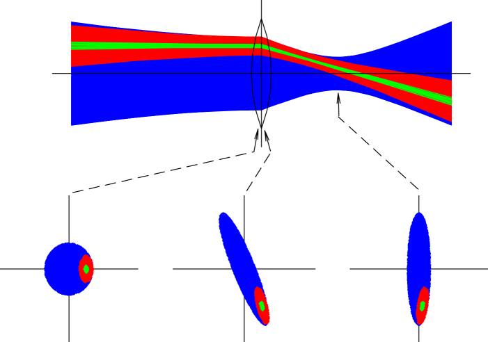
Steering vs. focusing
In the sketch below, the blue beam is a centred large-emittance beam. But
optics just maps phase space to phase space. The red beam
(with green center) is a subspace of
the blue and can be thought to represent a poorly-centred, small-emittance beam.
quads steer misaligned beams...
This shows that if the
beam is misaligned in a quadrupole, that quadrupole will steer, making it
difficult to achieve a proper focus. For example, if
the beam is displaced by more than a beam radius, the steering effect of a
quad is more important than the focusing effect. Under these conditions of
poor beam alignment, tuning quads to just maximize beam on the final beam stop is
not productive. Good tuning practice is to first steer to
correct the beam alignment through the quads, then tune the quads to
correct beam size. How do you tell the difference? Look at a profile monitor.
Tuning knobs
A beam particle, and so therefore also the beam centroid (consider the
centroid as the reference particle), can be characterized by two
coordinates in the x-direction (x,q), and two in the y-direction
(y,f). This means the beam misalignment can in principle be corrected
by 4 steering elements. But one cannot just pick any 4, since the elements
must be `orthogonal'. In the figure below, steerers 1 and 3 are not
orthogonal: downstream of steerer 3 they have exactly the same effect. If
the goal is to set up the beam to be aligned downstream of steerer 3, use
either 1 and 2 or 2 and 3. On the other hand, if the goal is to align the
beam locally between 1 and 3 without affecting alignment downstream of 3,
then using 1 and 3 is correct.
The beam width can be characterized by 3 parameters in each plane: one can
think of these as size, divergence, and emittance. However, the emittance
is not a tunable parameter. This leaves a total of 2 parameters in each
transverse plane. So in principle a beam can be matched using as few as 4
quadrupoles. Again, one must choose an `orthogonal' set of 4.
 4 steering knobs plus 4 focusing knobs = 8 knobs! Not a
trivial task...
4 steering knobs plus 4 focusing knobs = 8 knobs! Not a
trivial task...
Tuning ISAC
Example: Mass separator to LEBT. Tune IMS:Q11, IMS:Q12, IMS:Q15, IMS:Q16,
IMS:XCB14, IMS:YCB14, IMS:XCB18, IMS:YCB18. How long does it take to
maximize transmission through IMS slits 24 and 26?
Let's say you are looking at current on IMS:FC34, and ignoring the wire
scanners. Let's say each knob is evaluated at 10 settings, for a second each. So it
takes 10 seconds to tune this knob by itself. But to tune 2 knobs, we need
to evaluate 10×10=100 settings; it takes about a minute or 2. Then
for 8 knobs, it takes 108 seconds, that's 3 years!
Now imagine we actually use the wire scanners at slits 24 and 26. This way
we can tell the difference between a steering error and a focusing
error. That reduces the dimensionality by 4. So we can do it in 2×10⁴
seconds = 6 hours!
Now imagine we close the slit IMS:YSLIT11 to its proper setting. This
achieves 2 things: It puts the beam at the correct location and it makes
the beam have the correct size. Now we are down to a dimensionality of
2. 2×10² seconds = 3 minutes!
(Aside: there is no X (vertical) slit at YSLIT11. That was a big
oversight. If we had one, we could match out of the separator in a few
seconds.)
What about matching from slits 24 and 26 to the rest of ISAC? There are 4
orthogonal slits. Set them to the correct settings and they define the beam
in both position and size, reducing the dimensionality to zero. Setup time
= 100 seconds. IOW, if a tune brought beam upstairs with given slit
settings before, just load it, set the slits, and you are done. The only
possible reason it would not work is if something like a HV PS failed.
Conclusion
- Use slits at their correct settings.
- Use wirescanners.
Both of these techniques reduce the number of dimensions of parameter
space.
File translated from
TEX
by
TTH,
version 3.67.
On 19 Feb 2005, 00:08.